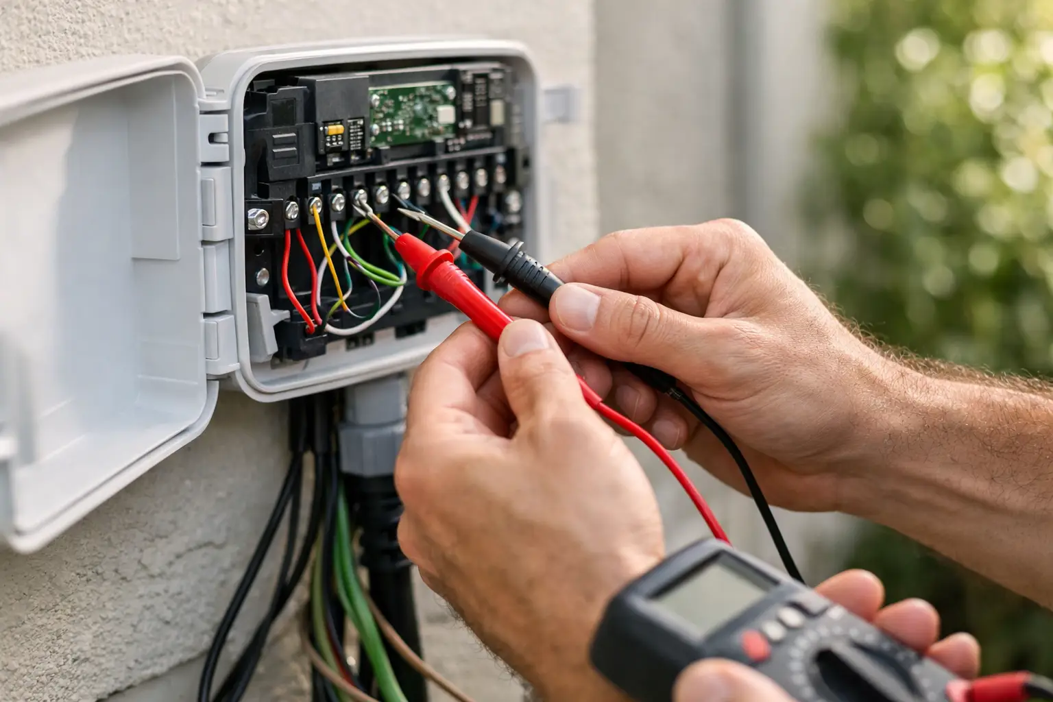
A zone that suddenly stops watering can turn a healthy lawn into a patchy problem quickly, especially during Colorado's hot, dry stretches. Knowing how to test sprinkler controller wiring helps you determine whether the issue starts at the timer, the valve wiring, or the valve itself before making unnecessary repairs.
Most residential irrigation controllers use low-voltage wiring, but that does not mean every test should be approached casually. The controller is connected to household power, and a poor connection can create intermittent failures that are difficult to diagnose. A methodical test protects the controller, prevents wire damage from getting worse, and gets water back to the landscape where it belongs.
Start With the Right Tools and a Safe Setup
A basic digital multimeter is the main tool for controller wiring tests. It should measure resistance in ohms and AC voltage. You will also want a small screwdriver, wire labels or masking tape, and a flashlight. If you will be opening valve boxes, keep a hand towel or rag nearby to clear dirt and moisture from wire connections.
Before touching any wires, photograph the controller terminals and label each wire. Most controllers have a terminal marked COM or C for the common wire, followed by numbered station terminals for individual zones. There may also be terminals for a master valve, pump start relay, rain sensor, or smart accessory.
Turn off power to the controller before performing resistance tests. Unplug a plug-in controller from its outlet. If the controller is hardwired, shut off the appropriate breaker and leave electrical-service work to a qualified professional. Never measure resistance on a live circuit. That can damage the meter and the controller.
Understand What the Controller Wires Do
Each irrigation valve needs two electrical paths. The common wire is shared by all valves, while each zone has its own station wire running from the controller to that specific valve solenoid. When the controller activates Zone 3, for example, it sends approximately 24 volts AC through the Zone 3 station wire. The circuit returns through the common wire, energizing the solenoid and opening the valve.
This simple layout makes diagnosis more straightforward. If one zone fails while the others work, the trouble is often limited to that zone wire, its splice, or its valve solenoid. If every zone fails, the problem may be the controller's power supply, a disconnected common wire, programming, or a shared component such as a master valve.
Wire colors are helpful but should not be treated as proof. A white wire is often used as the common wire, but installers may use any available color. Trust the terminal label and your notes rather than color alone.
How to Test Sprinkler Controller Wiring With a Multimeter
The most useful controller wiring test is a resistance test from the controller terminals. It checks the entire low-voltage path from the controller to the solenoid and back through the common wire.
Test each zone for resistance
With power off, set the multimeter to resistance, shown as the ohm symbol, Ω. Disconnect the wire for the problem zone from its station terminal. Also disconnect the common wire from the COM terminal. Separating these wires from the controller prevents the meter from reading through internal controller components.
Touch one meter probe to the zone wire and the other probe to the common wire. A working irrigation solenoid and wire run commonly read somewhere around 20 to 60 ohms. The exact reading depends on the solenoid model, wire length, and connection condition, so consistency between similar zones can be more useful than chasing one exact number.
A reading of OL, open loop, or extremely high resistance usually means there is a break somewhere in the circuit. The wire may be cut, a splice may have failed, or the solenoid coil may be open. A very low reading, often close to zero ohms, points to a short circuit. Damaged insulation, moisture inside a splice, or a failed solenoid can cause that result.
Repeat the test for each zone if more than one area is affected. Write down the readings. A single abnormal zone gives you a clear place to focus. If all zones show an open circuit, inspect the common wire connection first because it is shared by every valve.
Compare the controller's voltage output
Resistance testing tells you whether the field wiring and solenoid circuit appear intact. The next test checks whether the controller is actually sending power when commanded.
Reconnect the common wire and station wire after the resistance test. Restore controller power, set the multimeter to AC voltage, and manually run the affected zone from the controller. Carefully touch one probe to the active station terminal and the other to the COM terminal. A functioning controller output typically shows about 24 to 30 volts AC while that station is running.
If the controller delivers normal voltage but the valve does not open, the fault is likely beyond the controller. The solenoid may be weak under load, a wire splice may be intermittent, or the valve may have a mechanical or water-supply issue. If there is no voltage at the terminal during a manual run, check the programming, seasonal shutoff settings, rain sensor connection, and controller power supply before assuming the controller has failed.
Avoid allowing the meter probes to touch two station terminals at once. That can briefly short outputs together. Use steady hands and take the reading at the terminal screws, not by pushing probes into crowded wire openings.
Check the common wire carefully
The common wire deserves extra attention because one loose termination can affect the entire system. With power off again, inspect the common wire where it enters the COM terminal. It should be fully inserted, firmly secured, and free of corrosion or broken copper strands.
If several valves in the same area fail but other zones still work, there may be a shared common splice in a valve box. Many systems use one common wire that branches to multiple valves underground. A failed waterproof connector at that branch can create a confusing pattern where some zones work and others do not.
Trace a Fault Beyond the Controller
When the controller test points to an open or shorted circuit, the next stop is usually the valve box. Locate the valve serving the affected zone and inspect the solenoid wiring. Look for loose wire nuts, cracked connectors, exposed copper, standing water, and signs of rodent damage.
Good irrigation splices should use connectors designed for underground, wet environments. A standard indoor wire nut may work temporarily, but moisture can reach the connection and cause corrosion or intermittent operation. Replace damaged or questionable splices with proper waterproof connectors, keeping the connections above the lowest point of the valve box whenever possible.
If the valve-box connections look sound, a direct solenoid test can narrow the problem further. Disconnect the two solenoid leads from the field wires and measure resistance across the solenoid itself. If the solenoid reads open or nearly zero ohms, replace it. If it reads in a normal range, the buried wire run is more likely the issue.
Buried wire damage is common near landscape edges, recent planting work, fence repairs, and areas where aeration or digging has taken place. In Parker and surrounding Front Range communities, freeze-thaw movement can also expose shallow wires or stress older splices. Do not start digging blindly. Confirm the valve location, isolate the likely wire path, and protect all underground utilities before excavation.
Account for Master Valves, Sensors, and Controller Settings
A master valve or pump start relay can make a wiring problem look like multiple bad zones. If individual station outputs show proper voltage but no zone receives water, test the master valve terminal while a zone is running. It should receive voltage at the same time as the active station. A failed master-valve solenoid, broken master wire, or relay issue can stop water flow to the full system.
Rain and freeze sensors can also interrupt watering. Some controllers display a sensor status or allow the sensor circuit to be bypassed for testing. If the controller indicates that a sensor is active when conditions are dry and warm, inspect its wiring and settings. Bypass the sensor only long enough to diagnose the issue, then restore the system's weather protection.
Smart controllers add another layer: seasonal adjustment settings, weather delays, flow alerts, and app-based schedules can prevent a manual run from behaving as expected. Confirm that the controller is not paused, in rain delay, or assigned an incorrect start time before treating the issue as an electrical failure.
When Professional Irrigation Diagnosis Makes Sense
Homeowner testing can identify many obvious problems, but some faults need specialized equipment and field experience. Repeated blown fuses, a controller that loses power, a suspected damaged transformer, or wiring that tests inconsistently are good reasons to stop and schedule service. The same is true when a buried wire fault may require locating equipment rather than exploratory digging.
A professional irrigation technician can test voltage under load, trace wire paths, inspect valve operation, and confirm whether low pressure, a stuck valve diaphragm, or a wiring defect is causing the problem. This approach is especially useful when missed watering is affecting established turf, shrubs, or newly planted landscape areas.
After any wiring repair, run every zone long enough to verify valve operation, coverage, and shutoff. Reliable controller wiring is only one part of an efficient irrigation system, but it is the part that tells every other component when to work. A few careful meter readings now can help keep your landscape healthy through the next dry spell.